Documentation
Concepts
Signals
Connections between components carry signal. Normally, this would be audio signal in float encoding with the range of -1 through 1.
However, connections make no assumptions on the range. This is critical as it allows connections to be used to control values that are at the sample rate scale or frequency scale.
Included component library provides useful components that can be combined effectively to create signals for each range, using constants, generators and basic arithmetic functions provided by primitives.
Ports
Components can have three types of ports.
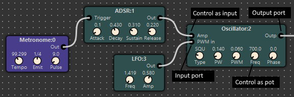
-
Input ports Input ports allow components to receive input. Input ports can operate at any scale, as defined by the component, though typically inputs are at signal scale (-1,1).
-
Output ports Output ports allow components to transmit output. Output ports can operate at any scale, as defined by the component.
-
Control ports Control ports control a parameter of the component. They can be used to provide visual user control, but can also be exposed as input ports and controlled by signal. Control ports have a minimum and maximum value. They can also be used as on/off and multi-position switches in some components where they are limited to specific, discrete values (for example wave shape in oscillator.
Connections
Connections can be used to connect ports. Underlying simulation framework maintain so-called junctions to which ports are connected, though this is not visible in the diagrams.
There are few conceptual limits to connectivity:
- No two output ports can be connected. Trying to do so will result in an error.
- Connections can only transport a single float number
The first limitation means everything else is allowed - output port can be connected to any number of input or control ports.
The second limitation is a bit tricky when it comes to transporting complex/multi-parameter signals such as midi messages.
Bench
Bench refers to test bench - components that are there to interact with your design, but are not part of the design itself. Examples are file and audio i/o and various instrumentation like Spectrum Analyser.
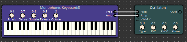
Bench components are visually identified by a different colour to the non-bench components. In the illustration above, the Monophonic Keyboard is a bench component, while the Oscillator is a standard / graph component.
Graph
Graph is a portion of the overall design that excludes all bench components.
Each design has an implicit “edge” - defined by connections between graph and bench components.
See examples for an illustration how this works.
Timebase
For projects that interact with audio hardware, timebase is automatic. That is, buffers are processed as they become available from audio input and are consumed by the audio output.
If your design doesn’t include audio hardware - for example operating on file i/o instead, you can choose from two modes:
- Full speed mode (throttling off) - in this mode, the simulation will not be tied to real time and - more often than not - can execute faster than real time. This is useful when rendering a long input file.
- Throttled mode - in this mode, the simulation will proceed in real time - as if there was a real device with a real timebase connected to the graph.
This option can be controlled via the Throttling option, in the settings dialogue (Edit -> Preferences), in the General tab.
Now proceed to the essential editing tips.